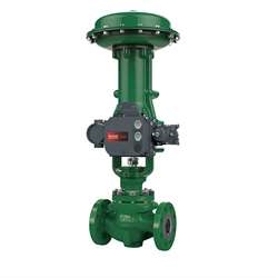
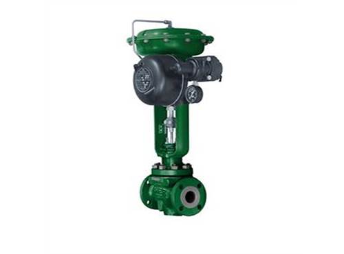
https://ttsui.futurismdemo.com/Media/Images/500X644//Fisher_40975.png

546

Fisher® 546

Fisher® 546 transducers receives a direct-current input signal and use a torque motor, nozzle-flapper, and pneumatic relay to convert the signal to a proportional pneumatic output signal. Nozzle pressure, which operates the relay, is also piped to the torque motor feedback bellows. This provides a comparison between input signal and nozzle pressure and corrects errors in nozzle pressure.

  • Vibration Resistance—High natural frequency of torque motor moving parts results in negligible vibration influence. Also meets typical seismic requirements for nuclear service.
  • Easy Adjustment—Screwdriver adjustments for span and zero are conveniently located and have arrows indicating rotation to increase settings.
  • Field-Reversible Action—No additional parts required to reverse action of 546 or 546NS; 546S versions cannot be reversed in the field but can be purchased either direct or reverse acting.
  • Simple Relay Removal—Integrated pneumatic relay is mounted outside case and can be removed without disturbing electrical or pressure connections or impairing explosion safety. 

Availability: In stock
Request A Quote

Specification

546

Available Configurations:

Electro-pneumatic signal transducer with explosion-proof case and coverThe 546 can be ordered with or without a Fisher 67filter regulator. A 51 mm (2 inch) circular supply pressure gauge may be mounted on the regulator.

Input Signals

4 to 20 mA DC

10 to 50 mA DC,

1 to 9 VDC,or

two-way split range using any half of one of the standard input signal spans

Internal Resistance of Torque Motor

4 to 20 mA DC Input Signal: 176 ±10 ohms

10 to 50 mA DC Input Signal: 90 ±10 ohms

1 to 9 VDC Input Signal: 1300 ±50 ohms

(temperature-compensated circuit)

Output Signals

Ranges:

0.2 to 1.0 bar (3 to 15 psig), 0.4 to 2.0 bar (6 to 30psig), 0 to 1.2 bar (0 to 18 psig), or 0 to 2.3 bar (0 to 33 psig)

Action:

The 546 is field-reversible between direct and reverse action.

Supply Pressure(1)

Recommended:

0.3 bar (5 psig) higher than upper range limit of output signal.

Maximum:

3.5 bar (50 psig)

Maximum Steady-State Air Consumption(2)

At 1.4 bar (20 psig) Supply Pressure:

0.6 normal m3/hr (21 scfh)

At 2.4 bar (35 psig) Supply Pressure:

0.8 normal m3/hr (30 scfh)

Maximum Output Air Capacity(2)

At 1.4 bar (20 psig) Supply Pressure:

12.9 normal m3/hr (480 scfh)

At 2.4 bar (35 psig) Supply Pressure:

18.5 normal m3/hr (690 scfh)

Performance(3)

Reference Accuracy:

±0.75% of output signal span

Independent Linearity:

±0.50% of output signal span

Open Loop Gain:

26

Frequency Response:

Gain is attenuated 3 dB at 20 Hz with transducer output signal piped to a typical instrument bellows with 305 mm (12 inches) of 1/4inch tubing<

Electromagnetic Interference (EMI):

Tested per IEC 61326-1 (Edition 1.1). Meets emission levels for Class A equipment (industrial locations) and Class Be quipment (domestic locations). Meets immunity requirements for industrial locations

Electrical Classification

Hazardous Area:

CSA— Explosion-proof, Dust Ignition-proof, Div 2

FM— Explosion-proof, Non-incendive

NEMA 3R, CSA enclosure 3
NEMA 3R mounting orientation requires vent location to be below horizontal.

Adjustments

Zero and Span Adjustments:

Screwdriver adjustments located inside case

Connections

Supply Pressure:

1/4 NPT internal located on side of case, (or located on the 67CFR filter-regulator if mounted)

Output Pressure:

1/4 NPT internal located on side of case

Vent:

1/4 NPT internal with screen located on relay

Electrical:

1/2 NPT internal located on bottom of case<

Approximate Weight

4.1 kg (9 pounds)

Resources

Our Brands

>