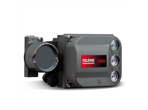
https://ttsui.futurismdemo.com/Media/Images/500X644//Fisher_40970.png

6200

?Fisher® FIELDVUE™ DVC6200

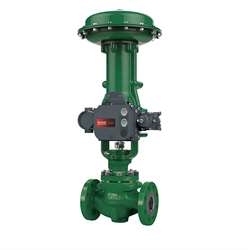
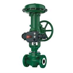
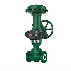
Fisher® FIELDVUE™ DVC6200 digital valve controllers are HART® communicating, microprocessor-based current-to-pneumatic instruments with linkage-less, non-contact travel feedback. Three important functions are performed by the DVC6200 instrument:

  • Traditional positioning of a control valve by converting the 4-20mA DC input signal from the process controller to a pneumatic output signal to the actuator.
  • Automatic calibration and configuration utilizing the power of microprocessor technology.
  • Communication capability via the HART communications protocol to provide instrument and valve diagnostic information.

This instrument provides one platform for any pneumatic actuator application. The DVC6200 can be installed on sliding-stem, rotary, single- or double-acting actuators

Availability: In stock
Request A Quote

Specification

6200

Available Mounting

DVC6200 digital valve controller or DVC6215feedback unit:

Integral mounting to Fisher 657/667 or GX actuators

Window mounting to Fisher rotary actuators

Sliding-stem linear applications

Quarter-turn rotary applications

DVC6205 base unit:

for 2 inch pipe stand or wall mounting (for remote-mount)

The DVC6200 digital valve controller or DVC6215feedback unit can also be mounted on other actuators that comply with IEC 60534-6-1, IEC60534-6-2, VDI/VDE 3845 and NAMUR mounting standards.

Communication Protocol

HART 5 or HART 7

Input Signal

Point-to-Point

Analog Input Signal: 4-20 mA DC, nominal; split ranging available

Minimum Voltage Available at Instrument Terminals must be 9.5 VDC for analog control, 10 VDC for HART communication.

Minimum Control Current: 4.0 mA

Minimum Current w/o Microprocessor Restart: 3.5 mA

Maximum Voltage: 30 VDC

Overcurrent protected

Reverse Polarity protected

Multi-drop

Instrument Power: 11 to 30 VDC at 10 mA

Reverse Polarity protected

Supply Pressure(1)

Minimum Recommended:

0.3 bar (5 psig) higher than maximum actuator requirements

Maximum:

10.0 bar (145 psig) or maximum pressure rating of the actuator, whichever is lower

Medium: Air or Natural Gas

Supply medium must be clean, dry and noncorrosive.

Per ISA Standard 7.0.01

A maximum 40 micrometer particle size in the air system is acceptable. Further filtration down to 5micrometer particle size is recommended. Lubricant content is not to exceed 1 ppm weight (w/w) or volume (v/v) basis. Condensation in the air supply should be minimized

Per ISO 8573-1

Maximum particle density size: Class 7

Oil content: Class 3

Pressure Dew Point: Class 3 or at least 10? less than the lowest ambient temperature expected.

Output Signal

Pneumatic signal, up to full supply pressure

Minimum Span: 0.4 bar (6 psig)

Maximum Span: 9.5 bar (140 psig)

Action: Double, Single Direct or Reverse

Steady-State Air Consumption(2)(3)

Standard Relay

At 1.4 bar (20 psig) supply pressure:

Less than 0.38 normal m3/hr (14 scfh)

At 5.5 bar (80 psig) supply pressure:

Less than 1.3 normal m3/hr (49 scfh)

Low Bleed Relay

At 1.4 bar (20 psig) supply pressure:

Average value 0.056 normal m3/hr (2.1 scfh)

At 5.5 bar (80 psig) supply pressure:

Average value 0.184 normal m3/hr (6.9 scfh)

Maximum Output Capacity(2)(3)

At 1.4 bar (20 psig) supply pressure:

10.0 normal m3/hr (375 scfh)

At 5.5 bar (80 psig) supply pressure:

29.5 normal m3/hr (1100 scfh)

Operating Ambient Temperature Limits(1)(4)

-40 to 85? (-40 to 185?)

-52 to 85? (-62 to 185?) for instruments utilizing the Extreme Temperature option (fluorosiliconeelastomers)

-52 to 125? (-62 to 257?) for remote-mountfeedback unit

Electromagnetic Compatibility

Meets EN 61326-1:2021>

Immunity— Industrial locations per Table 2 ofthe EN 61326-1 standard. Performance isshown in table 1-3 below.

Emissions— Class A

ISM equipment rating: Group 1, Class A

Lightning and Surge Protection— The degree ofimmunity to lightning is specified as Surge immunityin table 1-3. For additional surge protectioncommercially available transient protection devicescan be used.

Independent Linearity(5)

Typical Value: ±0.50% of output span

Input Impedance

An equivalent impedance of 500 ohms may be used.This value corresponds to 10V @ 20 mA.

Vibration Testing Method

Tested per ANSI/ISA-S75.13.01 Section 5.3.5. Aresonant frequency search is performed on all threeaxes. The instrument is subjected to the ISA specified1/2 hour endurance test at each major resonance.

Humidity Testing Method

Tested per IEC 61514-2

Electrical Classification

Hazardous Area Approvals

CSA— Intrinsically Safe, Explosion-proof,Division 2, Dust Ignition-proof

FM— Intrinsically Safe, Explosion-proof,Dust Ignition-proof, Non-Incendive

ATEX— Intrinsically Safe, Flameproof, Type nDust by intrinsic safety

IECEx— Intrinsically Safe, Flameproof, Type n

Dust by intrinsic safety and enclosure

Electrical Housing

CSA— Type 4X, IP66

FM— Type 4X, IP66

ATEX— IP66

IECEx— IP66

Other Classifications/Certifications

Natural Gas Certified, Single Seal Device— CSA, FM,ATEX, and IECEx

Lloyds Register— Marine Type Approval

CCC— China Compulsory Certification

CML— Certification Management Limited (Japan)

CUTR— Customs Union Technical Regulations(Russia, Kazakhstan and Belarus)

DNV— Marine Type Approval

ESMA— Emirates Authority for Standardization andMetrology - ECAS-Ex (UAE)

INMETRO—National Institute of Metrology, Quality,and Technology (Brazil)

KOSHA—Korean Occupational Safety & HealthAgency (South Korea)

NEPSI—National Supervision and Inspection Centrefor Explosion Protection and Safety ofInstrumentation (China)

PESO CCOE—Petroleum and Explosives SafetyOrganisation - Chief Controller of Explosives (India)

SANS—South Africa National Standards

Connections

Supply Pressure:

1/4 NPT internal and integral pad for mounting 67CFR regulator

Output Pressure:

1/4 NPT internal

Tubing:

3/8-inch recommended

Vent:

3/8 NPT internal

Electrical:

1/2 NPT internal or M20

Actuator Compatibility

Sliding-Stem Linear

Linear actuators with rated travel between 6.35 mm(0.25 inch) and 606 mm (23.375 inches)

Quarter-Turn Rotary

Rotary actuators with rated travel between45 degrees and 180 degrees(6)

Weight

DVC6200

Aluminum:3.5 kg (7.7 lbs)

Stainless Steel:8.6 kg (19 lbs)

DVC6205:

4.1 kg (9 lbs)

DVC6215:

1.4 kg (3.1 lbs)

Construction Materials

Housing, module base and terminal box:

A03600 low copper aluminum alloy (standard)Stainless steel (optional)

Cover: Thermoplastic polyester

Elastomers:Nitrile (standard)

Fluorosilicone (extreme temperature)

Options

Supply and output pressure gauges or

Tire valves

Integral mounted filter regulator

Low-Bleed Relay(7)

Extreme Temperature

Remote Mount(8)

Stainless Steel

Integral 4-20 mA Position Transmitter(9):

4-20 mA output, isolated

Supply Voltage: 8-30 VDC

Reference Accuracy: 1% of travel span

The position transmitter meets the requirements ofNAMUR NE43; selectable to show failure high( > 22.5 mA) or failure low (< 3.6 mA). Fail high onlywhen the positioner is powered.

Integral Switch(9):

One isolated switch, configurable throughout the calibrated travel range or actuated from a device alert

Off State: 0 mA (nominal)

On State: up to 1 A

Supply Voltage: 30 VDC maximum

Reference Accuracy: 2% of travel span

Resources

Technical Data-Sheet

6200

Fisher_6200_Positioners.pdf

download-icon

Technical Data-Sheet

6200

Fisher_6200_DVC.pdf

download-icon

Technical Data-Sheet

6200

Fisher_6200_Positioners.pdf

download-icon

Technical Data-Sheet

6200

Fisher_6200_DVC.pdf

download-icon

Our Brands

>